| nPowerTek
NPH-1 Heatsink From All Angles |
 |
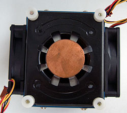
The Fan:
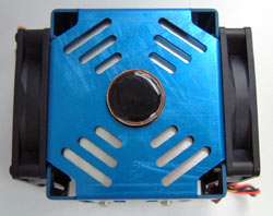
Looking at the top of the heatsink we can see the
25mm diameter heat column popping out. The blue aluminum fan shroud is
constructed with fairly thick (1.5mm) aluminum plate, and holds everything
in place. There are several cuts in the shroud to help with
airflow in the heatsink I'd imagine. |
 |
Heatsink Top:
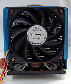
The two fans are mounted on the sides
of the heatsink so air moves parallel to the 30 aluminum fins inside. The 70mm fans are mounted so
that they blow in the same direction. The fans connect to a standard three-pin
motherboard header, but since most motherboards only have one available for the CPU fan you will need
to source out a Y-splitter of some sort. The heatsink we tested came with no
such accessories. |
 |
Side A:
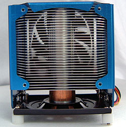
With the fan removed we have a better indication of how the NPH-1 heatsink is built. The
central 25mm thick heatpipe column acts as a
post for the aluminum fins to be pressed on to. In this way, the aluminum
fins have direct contact with the copper heatpipe and can easily absorb and disperse
the heat energy it absorbs from the processor. Fins are 0.5mm thick and spaced about 2mm
apart. |
 |
Side B:
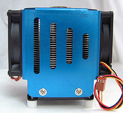
The side of the NPH-1 features several cut outs that
we can
only assume have some effect on the airflow within the
heatsink. The mounting system for the heatsink consists of several screws
held in place with small
nylon spacers. To install the heatsink you will need to remove
the motherboard and screw into the supplied rear support frame. It is a somewhat cumbersome method,
but the end result is a very sturdy mount that is not about to go
anywhere. |
 |
Heatsink Base:
The 33mm diameter copper base consists of a 5mm thick
disk attached to the remainder of the heatpipe, and provides a
good mounting point. The copper is very flat, and very smooth, so only a small amount of thermal
compound is really necessary. Note the small white plastic screws and
spacers at each corner of the base which are those used
to secure the NPH-1 to the motherboard. |


