| Thermal Integration TI-A8736N
Heatsink From All Angles |
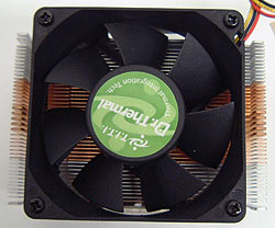 |
The Fan:
The 70mm fan is
the standard size for most modern mainstream heatsinks, though larger 80mm and even 92mm fans are starting to make headway. The fan
draws 0.6A and rotates at 4000 RPM to provide the necessary airflow to keep the TI-A8736N
cool. The fan connects to a standard 3-pin motherboard fan header. |
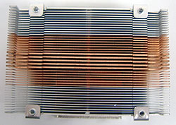 |
Heatsink Top:
After unscrewing the fan from the aluminum fan shroud which supports
it 4mm above the fin tips, we can get a better look at how
things work. The aluminum fins are positioned
towards the outer edges of the heatsink where there is no
direct contact with the CPU core. Directly over the center of the CPU
core are several thick copper fins that support the forces the retention clip
applies to the heatsink. Surrounding them is 10mm worth of copper fin on either side.
It is this copper area of the heatsink which comes in contact with the
processor core. |
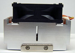 |
Side A:
The central slot appears to
be for manufacturing rather than venting issues. As the TI-A8736N weighs upwards of 515grams, it is
paramount to ensure the heatsink is firmly attached to the processor. Were a heatsink like
this to come loose and rattle around inside a computer case it would cause
a lot of damage. Also note the steel wedge and bolts which hold the heatsink
together. |
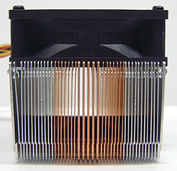 |
Side B:
Each aluminum fin measures 0.3mm thick, the copper ones 0.4mm and 1mm
respectively. Fins are spaced 1mm apart, with the central ones being thicker to support the clip
forces. The Fins are all about 35mm tall and the base ranges from 8mm to 14mm
thick. |
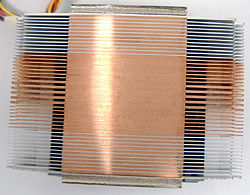 |
Heatsink Base:
The copper base extends only 45x60mm, instead of
the entire width of the heatsink. The base has been sanded down to a
pretty flat surface finish, though it is slightly domed as is typical of this operation.
There are no visible spaces between the copper and aluminum fins, and on either side of
the main base plate is about 20mm worth of open space
where warm exhaust air can exit the heatsink.
|


