|
|
82%
Abstract: From our standpoint the visual similarities between
this radial heatsink and the obs of long ago are pretty superficial.
|
Home >
Reviews >
Page: The heatsink from all sides
|
| JMC 400074 Heatsink From All
Angles |
 |
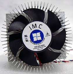
The Fan:
The fan is 67mm in diameter and surrounded by a
22mm high wall of aluminum fins. Each aluminum fin is about 0.6mm
thick and spaced about 3mm apart
from the next. Rotating at 4500RPM, the fan is glued in place and comes
with a nice long power cable that supports RPM monitoring.
As you might be able to see behind the impeller, the fins
go all the way back to the motor base. This helps to provides
a better exhaust path for air to leave the heatsink. |
 |
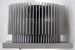
Side A:
There isn't too much to talk about
from the side here. The fins are 50mm in height with a small
10mm section cut from the bottom bit. This area of the fins
is removed so the heatsink will physically fit into a standard P4 HSRM. The
baseplate is 6mm thick and really only works as part of the retention system. A
separate retention system will allow this heatsink to be attached to Xeon processors.
|
 |
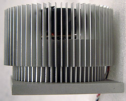
Side B:
It's easier to see why the bottom bits
of the finned section where machined
off. The diameter of the fins are a lot wider than the internal
dimensions of the HSRM. The three power cables coming from the fan are glued in
place to prevent them from potentially blocking the impeller (fan) from spinning. According
to the spec sheet I have, the entire fan assembly is glued in place
with Loctite Activator/Adhesive into a small recess. |
 |
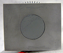
Heatsink Base:
The base is flatter than I would have expected, and it
looks as though the entire heatsink has had a dip in acid, or
received a fine sandblast since the surface is evenly finished. The surface is matt,
not shiny, but not rough either. The heatsink comes with a pre-installed circle
of thermal compound. The finned section is inserted into the aluminum
base with an interference fit. |
|
 |
Websites you may also like:
PCSTATS
|
|
 |


