|
Coolink H1T From All
Angles |
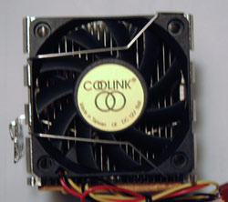 |
The Fan: The eleven-bladed fan measures 60mm
across and is held in place by a small spring clip. The fans draw power
from a standard three-pin connector which hooks up to the motherboard.
Since the body of the heatsink is rigid, there is no way to add a larger
70mm fan easily, and you will need to have a Y-splitter or two free power
headers free to plug the fans in. |
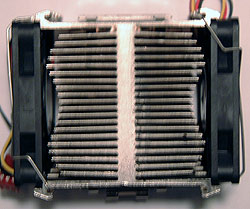 |
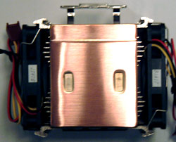
Top:
The classic "H" design of this heatsink doubles the surface area in direct
impact with the airflow in a minimum
of space. Each of the two fans are held in place with two small spring clips. The central portion
of the heatsink measures 6mm thick. The fins are roughly 23mm long, 1mm thick and spaced 2mm
apart. |
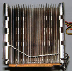 |
Side
A: The copper base of the
heatsink is 4mm thick and dip brazed to all of the bottom side fin edges. The three large cross cuts are only superficial, and are just there to allow the clip to lock into place. The main clip is locked into place within the heatsink and the holes cut for it also serve as exhaust vents.
|
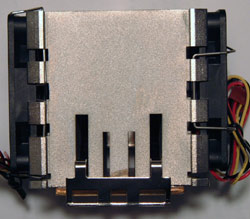 |
Side B:
The three-prong clip is pretty easy to work with
if you have
a screwdriver, and the three prongs mean that if you
have a board where the center socket clip has been snapped off you still have a
heatsink you can use. There is room for extra fins on this side of the heatsink, but
for some reason the manufacturer has decided to leave this area completely empty of cooling fins. |
 |
Heatsink Base:
The 4mm thick copper base has two really large indents from a stamping procedure
which is used to ensure proper alignment on the fin assembly. The
copper base is dip brazed to the nickel plated aluminum and so the thermal joint should be pretty consistent
all the way across. The base is just about perfectly flat in one axis, and
slightly curved in the direction that the sanding went. The base itself measures 48mm
x 57mm. |


